
Using AVR-USBasp to Program Arduino
Generally, there are two methods to load the program into Arduino: USB/Serial Communication method ISP method The first method is the most common method, which implemented using USB-to-serial adapter chip/converter. For

- USB/Serial Communication method
- ISP method
- Load Program into CT-UNO
- Load Program into BBFuino
- Load Program into Standalone Arduino
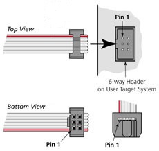
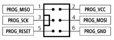
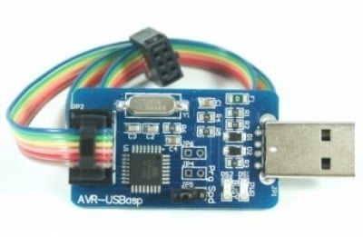 AVR USBasp is an USB in-circuit programmer and can be used to program most of Atmel AVR microcontroller. It simply consists of an ATmega8 and a couple of passive components, i.e. resistors, capacitors, LEDs and etc. This programmer uses a firmware-only USB driver and there is no special USB controller is needed. AVR USBasp came with 6-way cable. Figures below will tell you what all the holes in the cable head are:
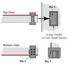 This figure is a view from the top and label each of the holes. Take note of the square as to what orientation your cable is in.
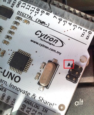
 The ISP header consist of 2×3 pins. You will notice there is a label of ‘1’ or an arrow label beside the ISP header. This label indicate the pin beside it is the pin 1 of the ISP header.
 Before proceed to the next step, make sure you install the AVR USBasp driver into your PC. If you haven’t, download the AVR USBasp driver and follow the instruction in the AVR USBasp User Manual.
Session 1: Load Program into CT-UNO
Before proceed to the next step, make sure you install the AVR USBasp driver into your PC. If you haven’t, download the AVR USBasp driver and follow the instruction in the AVR USBasp User Manual.
Session 1: Load Program into CT-UNO
- Insert the ISP programmer cable socket onto ISP header. The plastic nub of the rainbow cable head and the arrow label should be on the same side.

- You will notice the PWR LED is ON. If it is not, please check the connection between cable head and ISP header.
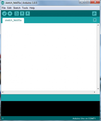
- Open Arduino IDE software. If you are using older version of Arduino IDE, you may receive some error. Download the latest version from Arduino website. I am using Arduino IDE version 1.0.5 and it works fine.
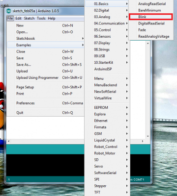
 3.Next, call out any example of source code. This tutorial will use the Blink example which can be called out from the File > Example > Basics > Blink menu.
 The sketch of Blink example:
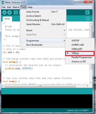
 4.Select “USBasp” from the Tools > Programmer menu.
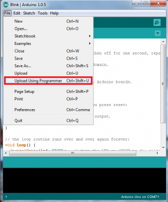
 5. Select “Upload using Programmer” from the File menu. The uploading process will takes a minute.
 If you select “Upload” or click “upload” button, you will receive an error as shown in figure below. This is because AVR USBasp is not installed as Serial port in our PC, and “Upload” function stands for upload the program via serial port. Do not worry, the IDE will still upload via USBasp.
 6.The uploading process is done when Arduino IDE display “Done uploading”
 Session 2: Load Program into BBFuino
BBFuino is using ATmega328 IC instead of ATmega328P IC (at the time this tutorial is written).
Session 2: Load Program into BBFuino
BBFuino is using ATmega328 IC instead of ATmega328P IC (at the time this tutorial is written).
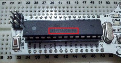 The difference between ATmega328 and ATmega328P is ATmega328P has the Atmel picoPower technology while ATmega328 does not have. The identification signature of ATmega328 and ATmega328P are different too. ATmega328 has the signature of 0x1E 0x95 0x14 while ATmega328P has the signature of 0x1E 0x95 0x0FB. Other than that, ATmega328 and ATmega328P are the same every sense architecturally. To upload sketches into ATmega328, some modification of configuration is needed:
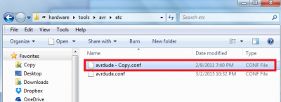
- Locate your Arduino directory. In my case, my Arduino directory is C:\Users\user\Desktop\arduino-1.0.5 Then, locate the directory hardware\tools\avr\etc. You will notice there is a file named “avrdude.conf” inside that directory.
 2. Make a copy of file “avrdude.conf” for backup purpose.
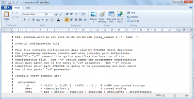
 3.Open the file “avrdude.conf” using WordPad
 4. Search for “m328p”.
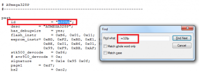 5. Look for “signature”. It should be few lines under “m328p”.
 Change 0x1e 0x95 0x0f to 0x1e 0x95 0x14
 6.
6.
- Click “Save” to save the edited configuration file and close it. Now you done modified the configuration of Arduino IDE.
 The procedure to upload sketches into BBFuino is similar with session 1:
- Open Arduino IDE software and call out any example. This tutorial will use the Blink example which can be called out from the File > Example > Basics > Blink menu.
 Select “USBasp” from the Tools > Programmer menu.
 Select “Upload using Programmer” from the File menu. The uploading process is done when Arduino IDE displays “Done uploading”.
 Session 3: Load Program into Standalone Arduino
In this session, the hardware required are:
Session 3: Load Program into Standalone Arduino
In this session, the hardware required are:
- ATmega328P IC x 1
- 1k? resistor x 1
- 16MHz crystal x 1
- 22pF capacitor x 2
- jumper wires
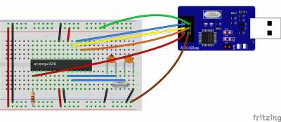
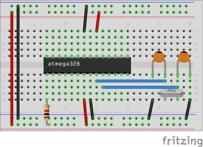 Figures below will be good reference when you connect AVR USBasp and standalone Arduino:
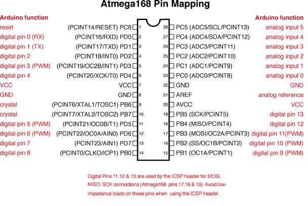 There is no ISP header on standalone Arduino. So we use male-to-male jumper wire to do some wiring between cable head and standalone Arduino. Refer to table below for the connection:
| ISP Programmer Cable Head | Standalone Arduino |
| Pin 1: MISO | PB4 (MISO / digital pin 12) |
| Pin 2: VCC | VCC |
| Pin 3: SCK | PB5 (SCK / digital pin 13) |
| Pin 4: MOSI | PB3 (MOSI / digital pin 11) |
| Pin 5: RESET | PC6 (RESET) |
| Pin 6: GND | GND |
 The procedure to upload sketches into standalone Arduino is similar with session 1. Select “USBasp” from the Tools > Programmer menu and choose “Upload using programmer” menu.
 The uploading process is completed when Arduino IDE displays “Done uploading”.
Great! I’m done sharing the ISP method to upload sketches into Arduino, hopefully it is helpful and if you have any inquiry, please do discuss in our technical forum as we seldom check the comment section in tutorial site. Please take note that there is a limitation for this method, that is the bootloader firmware is being replaced by the source code of the blink example. To go back to uploading sketches using USB, you’ll need to burn the bootloader into the chip on the Arduino board. Refer to Burning Arduino Bootloader with AVR USBasp to burn the bootloader onto Arduino using AVR USBasp.
The uploading process is completed when Arduino IDE displays “Done uploading”.
Great! I’m done sharing the ISP method to upload sketches into Arduino, hopefully it is helpful and if you have any inquiry, please do discuss in our technical forum as we seldom check the comment section in tutorial site. Please take note that there is a limitation for this method, that is the bootloader firmware is being replaced by the source code of the blink example. To go back to uploading sketches using USB, you’ll need to burn the bootloader into the chip on the Arduino board. Refer to Burning Arduino Bootloader with AVR USBasp to burn the bootloader onto Arduino using AVR USBasp.
About Robu
India's biggest robotics E-commerce company. Robu deals with Arduino, Raspberry Pi, Sensors, Drone parts, 3D printer parts, E-bike accessories and Electronics components etc. Click here to explore range of Robotics products available at Robu. Also, do not forget to follow us on Facebook, Instagram and YouTube because we are constantly contributing to the community by creating content around Arduino, Raspberry Pi, Drones, Sensors etc.
Related Posts
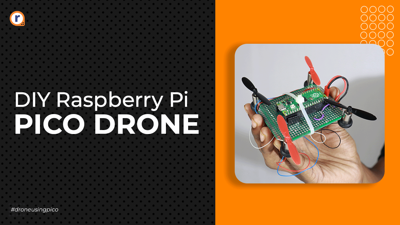
DIY Raspberry Pi Pico Drone-The Hardware
Tuesday August 31, 2021 5281 Views
Since the raspberry pi pico came into the market, it has become the buzz of the town. It has become ideal for many to get their hands on this newest... Read More
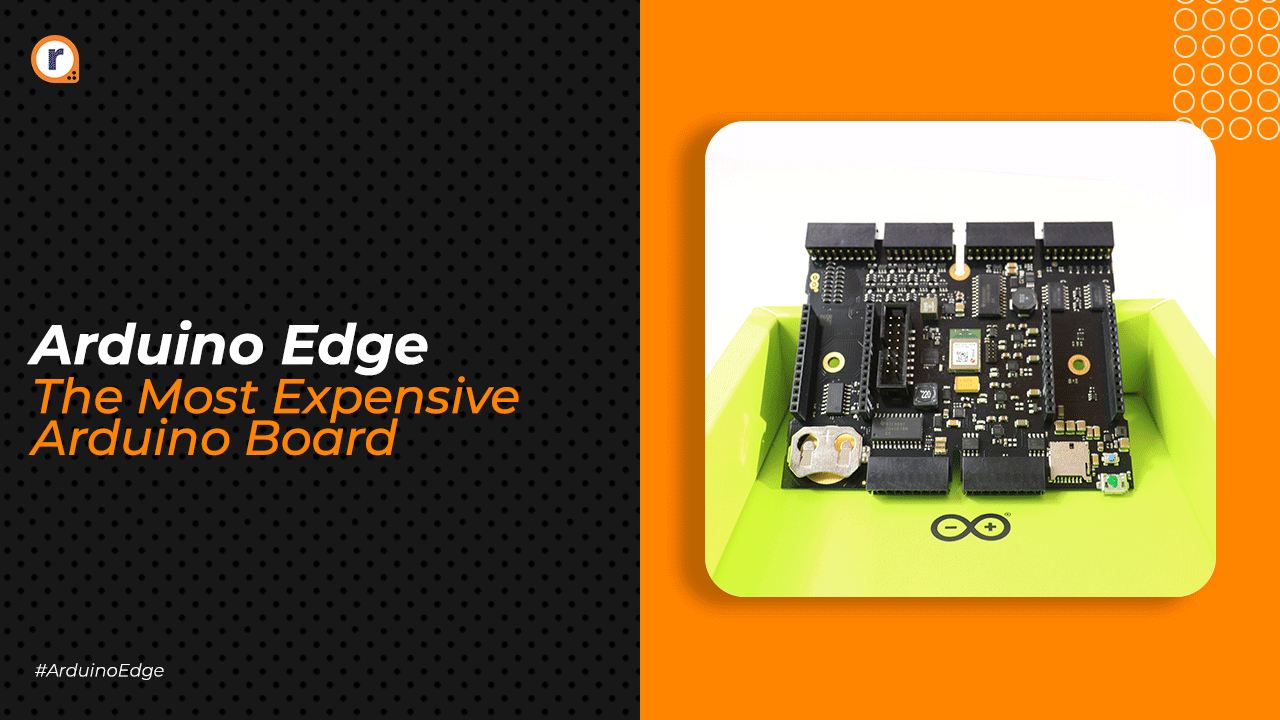
Arduino Edge-The Most Expensive and Useful Arduino.
Wednesday September 15, 2021 1548 Views
The Arduino edge is a board that has become the next best addition to the Arduino pro series for IoT development. This board as the official Arduino site claims “Controls... Read More
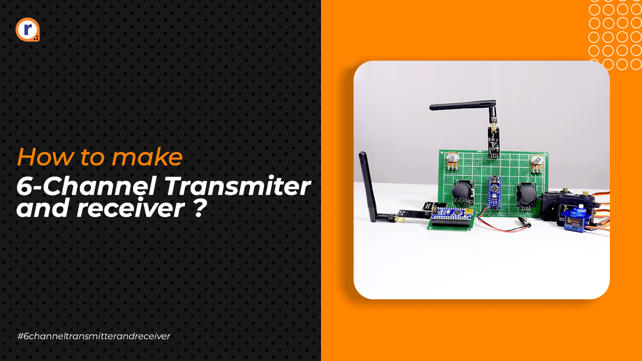
How to make 6 channel transmitter and receiver?
Thursday September 9, 2021 6189 Views
Transmitters and receivers have always been important for Rc hobbyist and engineers to control their projects. In this blog, you will be learning how you can build a 6 channel transmitter for yourself... Read More

The Latest Raspberry Pi OS Update Improves Zoom, Google Meet, and Microsoft Teams Experience
Sunday December 6, 2020 1107 Views
Significant improvements are made to the operating system for handling audio from multiple sources.... Read More
Well explained.
Thanks